
O-Ring Groove Machining: Dimensions and Tolerances Guide
A groove that looks right on the drawing can still leak. We see it regularly: a part arrives with a clean bore, sharp corners and a bright finish, then fails leak testing because the groove was cut to the wrong depth or left with tool marks running across the sealing face. O-ring groove machining looks simple, but it is one of the few features where a few ten-thousandths of an inch decide whether the seal holds. This guide covers how to read AS568 dimensions, where tolerances actually matter, what surface finish to specify, and how to inspect grooves before they ship.
Table of Contents
Quick Takeaways
Key Insight | Explanation |
|---|---|
Start from the O-ring part number | Groove diameter and depth come from the ring's inside diameter and cross section. Do not start from the mating bore alone. |
Confirm static or dynamic service first | The FST AS568 design guide is written for static applications under 1500 psi. Dynamic seals and higher pressures need different groove geometry. |
Depth controls squeeze more than width | On most static grooves, depth tolerance is the number that determines whether the ring is compressed enough to seal. |
Finish the sealing face, not just the floor | Tool marks that run across the seal path give the elastomer a place to extrude or tear. Specify lay direction as well as roughness. |
Design the corners for the ring | Sharp internal corners pinch rings and concentrate stress. Corner radii and tool deflection define the real groove shape. |
Gauge depth and diameter before assembly | Pin gauges and CMM checks catch out-of-tolerance grooves early, and the results belong in your PPAP or first article package. |
Why Grooves Fail Before the Part Ships
Most groove failures we see are not exotic. The groove is a few thousandths too deep, the floor has a chatter pattern, or the inside corner was cut with a tool that left a small radius the ring cannot tolerate. The part passes a visual check and fails in the field, where the seal is asked to hold pressure for thousands of cycles.
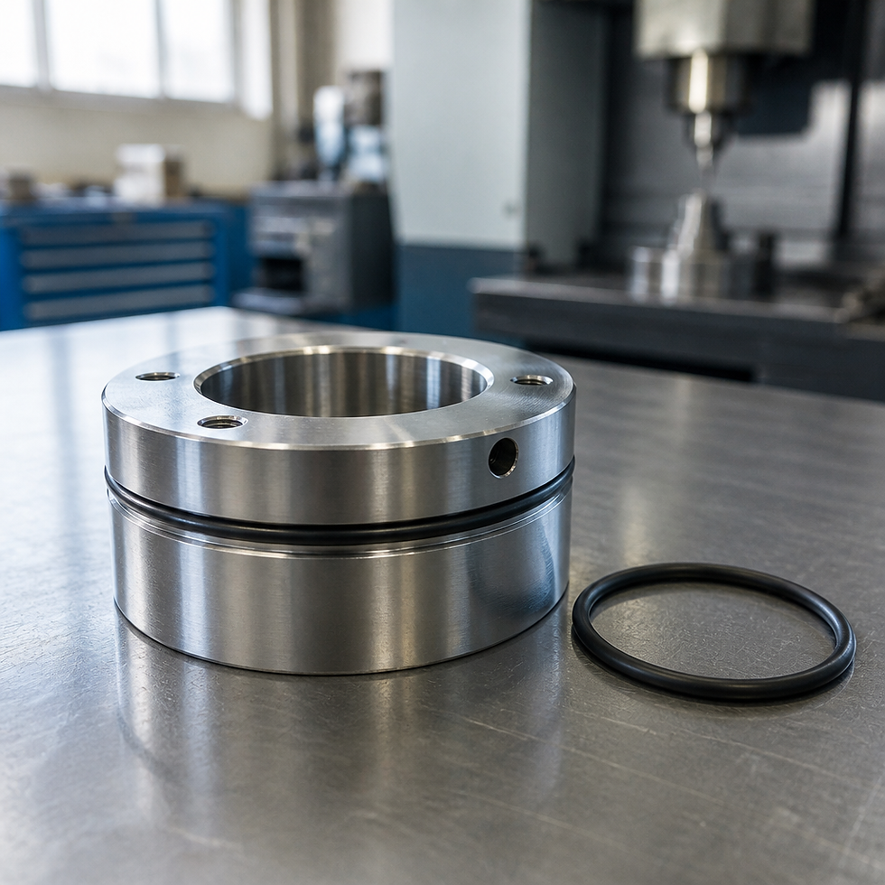
The common failure modes are predictable. Extrusion happens when the gap between the mating parts is too large for the pressure, and the ring pushes into it. Nibbling happens at the edges of the gap when the elastomer cycles against a sharp edge. Spiral failure, where the ring twists and cuts itself, usually traces back to a dynamic groove with the wrong squeeze or a rough finish on the moving surface.
In practice, the fastest way to find the cause is to look at the groove before the ring goes in. A common mistake is to assume the seal supplier caught the problem. They only see the ring. The groove is your job, and it is the part of the assembly most likely to be cut to a drawing that was never checked against the ring it is supposed to hold.
Pro tip: Before you release a groove program, compare the drawing against the ring part number, the pressure, and whether the joint is static or dynamic. Most avoidable failures are caught at that step.
Reading AS568 Dimensions Correctly
The AS568 standard is the reference most North American drawings use for O-ring sizes. Each ring is identified by a dash number that maps to an inside diameter and a cross section. The dash number tells you what the ring is. It does not tell you what the groove should be, and that distinction is where many drawings go wrong.
The groove is designed from the ring's cross section and the gland geometry your application needs. A ring measured on a bench is not always the ring on the drawing. Elastomers stretch during installation, and older rings can take a set. If you need to verify a ring, measure it, then reconcile the measurement against the published standard before you trust either number.
Inside Diameter and Cross Section
The inside diameter of the ring sets the groove diameter, and the cross section sets the groove depth and width. The common 2-series rings used in many hydraulic and industrial housings have a cross section of 0.139 inch, so the groove depth you cut has to account for that value and the squeeze your design calls for. If the drawing shows only a bore diameter and a depth, ask for the ring part number before you program the cut.
The jlcmc size guide explains how to measure a ring, calculate missing dimensions, and read both AS568 and metric size information. That is useful when a customer sends a ring with no part number, but measuring should be a backup. The reliable source is the part number on the drawing.
Static and Dynamic Applications
The FST quick reference guide is written for static applications with pressures less than 1500 psi. That limit matters. A static face seal in a bolted flange is a different problem from a reciprocating rod seal, and a groove designed for one will often fail in the other. Dynamic grooves usually need tighter control over surface finish and wall geometry, and the squeeze you choose has to account for friction and heat.
When a drawing does not state static or dynamic service, do not guess. Send the question back to engineering. We have seen grooves cut for a face seal used on a moving shaft simply because nobody asked which one the customer needed.
Groove Depth, Width, and Squeeze
Squeeze is the compression of the ring between the groove floor and the mating surface. It is the main thing the groove is designed to produce. Too little squeeze and the ring cannot seal at low pressure. Too much and the ring takes a permanent set, extrudes faster, or simply tears during assembly.
The groove depth sets squeeze. Once the ring is selected, depth is the number that moves the seal from marginal to reliable, and it is also the feature most sensitive to machining error. A depth error of a few thousandths can change the compression by a meaningful percentage on a small cross section.
Why Depth Is the Number That Matters
Depth is where we concentrate inspection effort. On a face groove, the depth is measured from the sealing surface to the floor, so any error in the floor carries straight into the squeeze. On a multi-level housing, a depth error on one diameter can shift the compression on the whole seal.
A practical habit is to check depth at more than one point around the groove. A single measurement can hide a tilted floor or a floor that dips where the tool deflected. If the depth reads within tolerance at one clock position and out at another, the problem is usually the setup or the tool, not the gauge.
Width and Corner Radius
Width gives the ring room to expand and move. Too narrow and the elastomer has nowhere to go when it compresses, which drives up stress and shortens life. Too wide and the ring can roll or twist under pressure. Width is usually less critical than depth, but it should not be treated as a leftover dimension.
Corner radii are where many grooves fail. A sharp internal corner pinches the ring and creates a stress point. A radius that is too large reduces the sealing area and can let the ring roll into the corner. The radius your program produces depends on the cutter geometry, so the corner shape should be part of the tool selection, not an afterthought.
Tolerances That Hold Up on the Production Floor
Tolerance on an O-ring groove is a system problem. The groove diameter, the depth, the bore that mates with it, and the position of the groove all combine to determine the squeeze on the ring. A tight tolerance on one feature does not help if the others are loose enough to stack up in the wrong direction.
The most useful habit is to build the stack-up before the drawing goes to the floor. List every dimension that touches the seal, assign tolerances, and calculate the worst case squeeze at both ends. If the worst case falls outside the range the seal supplier recommends, the drawing needs to change, not the operator.
Stack-Up From Bore, Depth, and Diameter
Start with the depth tolerance because it usually has the most influence. Then add the bore and groove diameter tolerances, which set the gap and affect extrusion risk. Finally, check the position of the groove relative to the datum, because a groove that is off-center relative to the sealing surface can compress unevenly.
In practice, we find that the diameter tolerance is the one most often loosened without thought. Because the diameter is easy to measure, drawings often carry generous tolerances there. The problem is that diameter changes the gap, and a larger gap is exactly where extrusion starts.
Gauging Depth and Diameter
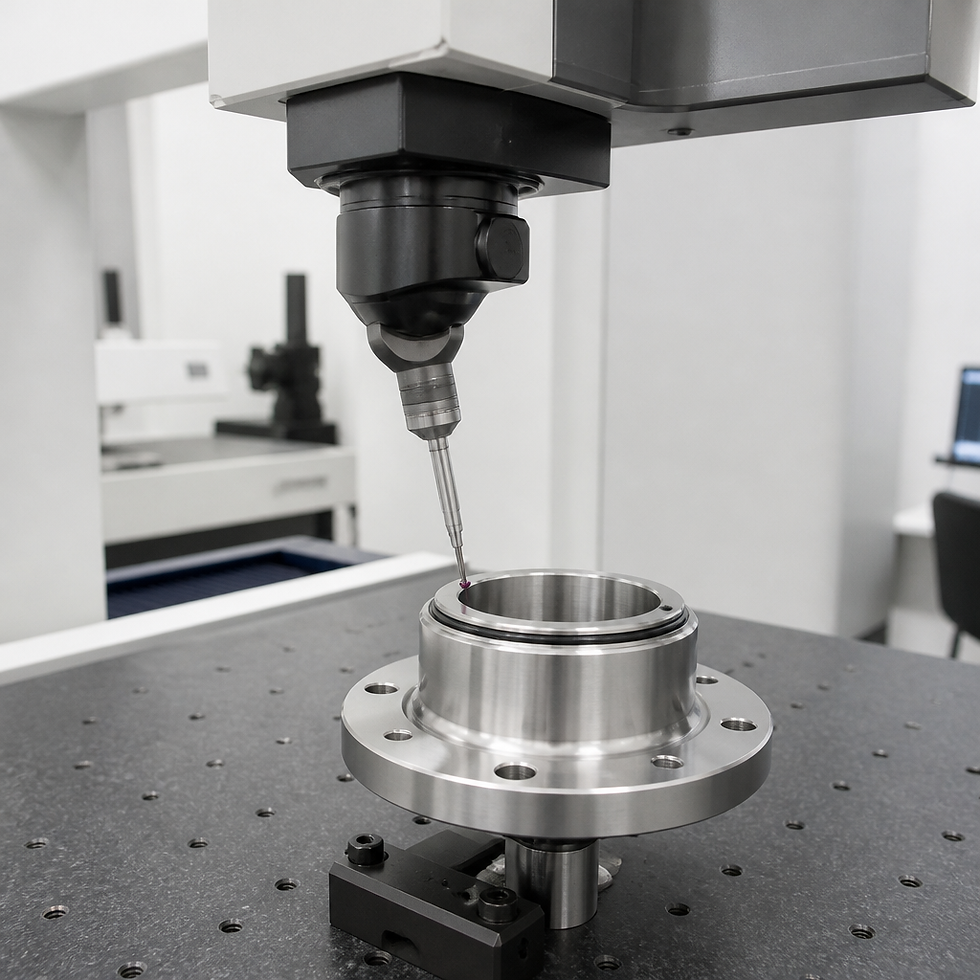
Depth is best checked with a method that reads the actual floor, not an estimate from the tool offset. Depth gauges and CMM probes both work, but they measure different things. A CMM gives you a full map of the floor and the walls, which is valuable when you suspect tilt or uneven cutting. A handheld gauge is faster for in-process checks on production runs.
Diameter checks are simpler, usually with a pin or a bore gauge. The gauge should be calibrated and the measurement repeated. At SCPM, the gauges used for these checks go through calibration support in our MetroLab division, which matters because a gauge that drifts quietly will pass bad grooves for days before anyone notices.
Surface Finish Standards for Sealing Surfaces
Surface finish on a groove does two jobs. It affects how well the ring seals against the surface, and it affects how the ring wears or tears when it is installed and moved. A rough surface gives the elastomer small points to grab and abrade. A surface that is too smooth can trap a film and change the friction behavior on dynamic seals.
Most drawings call out a roughness value for the sealing surfaces. That number is useful, but the lay direction and the absence of tool marks across the seal path matter just as much. A finish that measures well in the roughness tester can still leak if a spiral mark runs straight across the sealing face.
A groove can meet its roughness callout and still fail if the tool marks run in the wrong direction across the seal path.
Sealing Faces Versus Groove Bottoms
The sealing face is the surface the ring contacts under pressure. The groove bottom is the floor the ring sits on. They do not always need the same finish, and treating them as one callout is a common drafting shortcut. Specify the sealing face clearly, then decide whether the groove bottom needs a matching value or a looser one based on the application.
Check the finish callout against the seal supplier's guidance rather than picking a number from memory. Suppliers publish recommended finishes for their elastomers and gland types, and those values reflect how the ring actually behaves. A number that looks reasonable on paper may be too rough for a soft compound or too smooth for a dynamic application.
Tool Marks and Feed Direction
Circumferential tool marks are usually acceptable on a static face. Spiral marks that cross the seal path are a problem because they create a leak path and a tearing edge at the same time. The fix is almost always in the tool path: change the feed direction, reduce the step-over, or finish with a light pass at a controlled speed.
A dull insert is the most common cause of a poor groove finish that operators do not notice. The surface looks fine until you run a finger along the sealing face or check it under magnification. We replace grooving inserts on a set schedule for sealing work, not when they break, because a worn insert produces a finish that passes a quick look and fails in service.
Machining Methods: Form Tools, Interpolation, and Wire EDM
There is no single right way to cut an O-ring groove. The method depends on the part geometry, the material, the volume, and how tight the tolerances are. A lathe with a form tool is fast for simple face grooves on round parts. A mill with CNC interpolation handles complex layouts and flat plates. Wire EDM is slower but useful when the material is hard or the walls are thin.
The table below compares the three approaches we use most often for sealing grooves. The choice should follow the part, not the machine that happens to be free.
Method | Best Use | Main Risk |
|---|---|---|
Form tool plunge on a lathe | Simple face and OD grooves on round parts where cycle time matters | Tool deflection and chatter on deep or narrow grooves, plus a fixed corner radius that may not match the ring |
CNC interpolation with a grooving insert | Grooves on mills, multi-feature parts, and flat plates where the groove path is not circular | Programming errors in corner geometry and a floor that tilts if the tool is not perpendicular to the surface |
Wire EDM | Hard materials, thin walls, and complex profiles where cutting forces would distort the part | Slower cycle time and a recast layer that may need removal before sealing |
Form Tools and Deflection
Form tools are efficient, but the geometry is fixed. If the groove you need does not match the tool, you cannot correct it by adjusting feed. Deep, narrow grooves push the tool into deflection, and the result is a floor that is deeper at one end than the other. Shorten the tool stick-out where you can and use a rigid holder.
A form tool that is worn or not dressed properly will produce a groove that looks correct in the first part and drifts over a run. Build a tool change interval into the process and check the first and last parts of every batch.
Interpolation and Tool Perpendicularity
Interpolated grooves give you flexibility, especially on mills with rotary axes. The risk is perpendicularity. If the tool axis is not square to the sealing surface, the floor tilts and the squeeze varies around the groove. On five-axis work, we check the tool orientation during setup, because a small angular error in the fixture can produce a groove that passes a single-point depth check and fails a full floor inspection.
Wire EDM for Hard and Thin Parts
Wire EDM makes sense when cutting forces would distort the part or when the material is too hard for conventional tooling. It can produce clean grooves in hardened steel and thin walls where a cutter would push the part out of position. The tradeoff is time and the surface left by the process. Plan for a finishing pass or a check of the recast layer if the groove will see dynamic service.
Dovetail and Vacuum Grooves on Flat Plates
Flat plates bring their own problems. Vacuum fixtures, sealing plates and dovetail-style grooves need the ring to stay in place under load and handling, and the groove geometry is less forgiving than a simple face groove. The ring has to be retained while the plate is assembled, and the groove has to hold the ring without pinching it.
A thread on a CNC machining forum makes a point we agree with. A contributor who uses dovetail grooves in vacuum fixtures advised cutting to published specifications rather than inventing the geometry. Home-made dovetail profiles tend to have the wrong angle or the wrong depth, and the ring fails in a way that looks like a seal problem when the groove is the real cause.
Dovetail Geometry and Retention
A dovetail groove retains the ring mechanically, so the angle and the depth have to work together. If the dovetail is too shallow, the ring can pop out during handling. If it is too deep or the angle is off, the ring is over-compressed in the corners. Use a published profile from a seal manufacturer where one exists, and verify the profile with a gauge or a projector before the first production run.
Vacuum Fixture Grooves
Vacuum fixtures put the ring under a different load than a pressurized housing. The pressure difference is small, but the ring must seal reliably at every cycle, and any leak shows up as a loss of holding force. Check the groove after several cycles of load and unload, because a groove that holds in a static check can still work its way loose in service.

Inspection and Documentation for PPAP and First Article
Inspection is where groove quality becomes provable. A groove that was cut to the right depth but cannot be shown with records is a problem for the customer and for you. Automotive and aerospace customers expect a documented trail from the drawing to the measured feature, and that trail is what PPAP and first article inspection are built to provide.
SCPM is A2LA accredited and supports PPAP documentation and first article inspection. For groove features, the documentation should show the measured depth, diameter, width and finish at defined points, along with the gauge or CMM program used to make the measurement.
First Article Measurement Plan
Build the measurement plan from the seal function. Depth should be measured at multiple points around the groove. Diameter and width should be checked at the locations that define the gap and the ring retention. The finish callout should be checked on the sealing face, not just the groove floor, and the lay direction should be noted if it matters for the application.
The first article is also the time to confirm the ring. Record the ring part number used for the check, and if a ring is measured, note the measurement method. That prevents a later argument about whether the groove or the ring was out of spec.
PPAP Records and Gauge Control
PPAP packages are only as strong as the gauges behind them. Keep calibration records for every gauge used on the groove, and make sure the gauge range and resolution match the tolerance. A depth gauge with a resolution that is too coarse for the tolerance cannot prove conformance, however carefully it is used.
Pro tip: Ask for the ring part number on every groove drawing, and write it into the inspection record. When a groove fails later, that single line tells you whether the problem was the ring, the groove or the assembly.
Pro tip: Check the first and last part of every batch for depth and finish on the sealing face. Drift in a form tool or insert shows up there long before a sample check finds it.
Frequently Asked Questions
What is the most important dimension in O-ring groove machining?
Groove depth is usually the most important dimension because it sets the squeeze on the ring. A small depth error can move a static seal from reliable to marginal, so depth should be measured at several points around the groove.
How do I know whether a groove is for a static or dynamic seal?
Check the drawing and the application notes first. If the drawing does not say, ask engineering before you program the cut. Static grooves are often designed from AS568 guidance for pressures under 1500 psi, while dynamic grooves need tighter control over finish and geometry.
Is wire EDM a good choice for O-ring grooves?
Wire EDM works well for hard materials, thin walls and complex profiles where cutting forces would distort the part. It is slower than conventional grooving, and the surface may need a finishing pass or a check for a recast layer before sealing.
What surface finish should I specify for a sealing face?
Use the finish recommended by the seal supplier for your elastomer and gland type, and specify the lay direction along with roughness. Spiral tool marks across the seal path can leak even when the roughness value passes.
What documentation should I keep for groove inspection in a PPAP package?
Keep the ring part number, the measured depth, diameter, width and finish at defined points, the gauge or CMM method used, and calibration records for each gauge. Those records show the groove conforms to the drawing and make any later failure investigation faster.
Have you run into a groove that passed inspection and still leaked in service? Tell us what the failure looked like and what your team found, because those cases are often the ones that improve the next drawing.


Comments