
Precision Machining for Robotics: Repeatability Under Load
Robot arms rarely fail on the first cycle. They drift on the ten-thousandth, when a bushing has worn a few microns, a bracket has crept under heat, or a locating pin has settled into a slightly different seat. For anyone doing precision machining for robotics, the real question is not whether a part measures correctly once, but whether it still returns to the same position after millions of cycles. This article covers how we think about repeatability in machined robot and automation components, where it gets lost, and which machining and inspection decisions protect it.
Table of Contents
Quick Takeaways
Key Insight | Explanation |
|---|---|
Repeatability sets the floor | Robot datasheets often list repeatability in the ±0.02 mm to ±0.05 mm range, and your machined interfaces need to hold inside that band, not around it. |
Stack-up beats single-part tolerance | A part can pass its print and still move the arm once adapter, flange, and fixture errors add together. |
Heat and load move mounting faces | Housings and mounts shift as motors and gearboxes warm, so state the temperature at which critical features are verified. |
Locate on the same features every cycle | Use one datum scheme for machining, inspection, and assembly, or every setup adds its own error. |
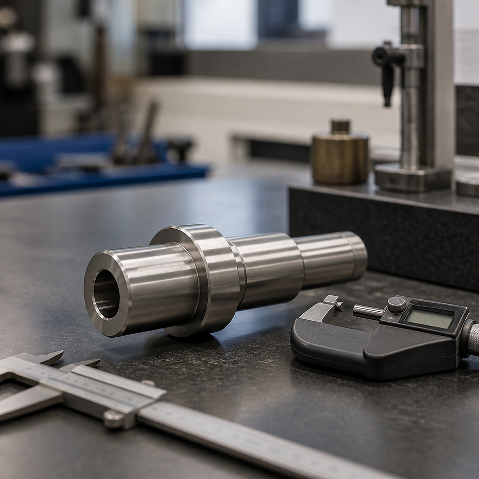
Match the process to the feature | Use lathe turning for concentric bores and shafts, 5-axis milling for compound geometry, and wire EDM for hardened or fine internal profiles. |
Measure the interface the arm sees | Build CMM programs around how the part is loaded and located, not only around the drawing callouts. |
Repeatability vs Accuracy in Robot Specs
Most robot datasheets lead with repeatability, and for good reason. Repeatability is how tightly a robot returns to a taught position across many cycles, while accuracy is how close it lands to a commanded coordinate in space. Dynalog's engineering write-up notes that robot manufacturers typically specify precision, which it equates with repeatability, in a range of ±0.02 mm to ±0.05 mm. A UR5e, for example, is listed at ±0.03 mm repeatability in a recent industry overview.

Doosan Robotics' blog makes the case that in industrial work, repeatability is the more decisive specification, because operators teach positions directly and then need those positions reproduced tens of thousands of times. We agree with that framing for machining work, with one caveat. The arm's repeatability is only one link in the chain. When parts come back from customers with problems, the failures rarely come from the arm itself. They come from the interface between the arm and the part.
Reading a Datasheet Repeatability Figure
A repeatability number means little without its test conditions. Ask whether it was measured at a single pose or across the full workspace, at rated payload or empty, and at what speed. Two datasheets with the same ±0.03 mm figure can describe very different test conditions, so compare them on identical terms before you design a mounting interface around either one.
For machined components, the practical question is simpler. Does the flange, bracket, or tool plate hold its datum position through the same thermal and load history the arm sees on the production floor? If the answer is unknown, the datasheet number is a starting point, not a design input.
Where Absolute Accuracy Still Counts
Repeatability does not fix a part that was in the wrong place from the start. When a robot must pick from a fixture, place into a pocket, or reach a feature machined on a different setup, absolute error becomes part of the budget. Calibration routines and offsets can recover some of that error, but they cannot compensate for a bracket bored at the wrong center distance. Get the nominal geometry right first, then protect the repeatability.
Where Cycle Loads Break Repeatability
Cycle loads are the repeated forces, accelerations, and temperature swings a robot puts into its own structure every shift. Each motion is small. Multiplied by millions of cycles, the effects accumulate in places a drawing rarely calls out.
Repeatability belongs to the whole chain, from the motor to the last machined face. The weakest link in that chain sets the number the customer actually sees.
Thermal Growth in Mounts and Housings
Gearboxes and motors warm up over a shift, and aluminum housings expand faster than steel mounts. A flange that was square at startup can measure differently after hours of continuous motion. We ask customers for the operating temperature range of every mounting interface, because a dimension inspected in a quiet room may not be the dimension the robot sees on a hot line.
Wear at Pins, Bearings, and Bushings
Locating pins and bushings take the repeated contact. A hardened pin running in a soft aluminum bore will open that bore over time, and the robot will drift in the same direction. Specify hardness and surface finish on contact features, and schedule replacement intervals in the maintenance plan instead of waiting for a reject.
Fatigue and Loosening of Fasteners
Vibration from fast moves loosens fasteners that were torqued once at assembly. Thread engagement, locking method, and clamp load all matter. A bracket that was tight at first article can be a different part by the end of the month. Designing for repeatability means designing joints that stay tight, not just joints that go together.
Machining Tolerances for Robot Parts
Machining decisions set how much error a part brings into the assembly before the robot ever moves. The goal is not to hold the tightest tolerance on every feature, which is expensive and rarely necessary. The goal is to hold the features that locate, load, and seat against each other.
Bore and Pin Fit Tolerances
For a locating bore and dowel pin, fit determines repeatability more than absolute size does. A clearance fit loose enough to rock will reintroduce play after a few thousand cycles. In practice we tighten the diameter and position tolerances on the pair together, and we specify bore finish, because a rough bore can wear faster than a smooth one.
Datum Schemes and Flatness
Each setup in a machine shop is an opportunity for error. When the datum used to machine a bracket is not the datum used to inspect it or mount it on the robot, the stack-up stays hidden. We build one datum scheme into the drawing and machine critical faces in as few setups as possible. Flatness on a mounting face matters more than people expect, since a slight high spot can rock the part under load and shift everything downstream.
Pro tip: Write the datum scheme on the drawing before quoting. If the robot mates to a face, that face should be a datum in machining, inspection, and the customer's assembly fixture.
Material Choice and Stress Relief
Aluminum machines fast and light, which suits moving arm components, but thin walls can distort as material is removed and internal stress releases. Alloy steels and stainless resist wear better at contact features, though they can be harder to hold to fine tolerance without distortion. A common mistake is choosing material for weight alone and then discovering the part moves after it leaves the fixture. For critical brackets, we often rough, relieve stress, and finish in a second pass.
Fixturing for Repeat Cycles
Fixturing is where repeatability is either protected or quietly lost. The fixture that holds a part during machining sets its orientation, and the fixture used at inspection and at the customer's assembly determines whether those orientations match. A part that is perfect in our fixture can still misbehave in a customer's cell if the locating scheme differs.
Lock the customer to the same locating features in every fixture, and specify which features are primary, secondary, and tertiary. Three points on a flat face, two on a side, and one on an end is a classic arrangement because it constrains the part without over-constraining it. Over-constraint causes a part to seat differently depending on which screw is tightened first.

Locating on the Same Features Every Cycle
Pick locating features that are part of the function, not leftover material. A machined pocket or a pair of bores that the robot actually references makes far better datums than an edge left over from the blank. If a feature exists only to hold the part during machining, either remove it or show it on the drawing as a temporary reference.
Adapter and Flange Stack-Up
Robot tool flanges, adapter plates, and tool changers each add a face, a bolt pattern, and a tolerance. Stack them together and the tool center point can end up well away from where the drawing says it should be. This is why repeatability alone does not eliminate errors introduced by adapters and fixtures. Treat the adapter as part of the measured system, and inspect it as an assembly.
Clamp Force and Tightening Sequence
Clamping order matters. Tightening one bolt pulls the part toward it, and an undocumented sequence will be done differently by every operator. We write tightening sequences and torque values onto the work instruction, then verify the assembled position after the first torque cycle and again after a warm-up run.
Choosing Machining Approaches
No single machining process makes every robot component well. The right choice depends on geometry, material, and how each feature must relate to its datums. The table below compares three approaches we use most often for this kind of work.
Approach | Best Fit | Main Trade-off |
|---|---|---|
5-axis CNC milling | Compound geometry, multi-face brackets, and reduced setups | More programming and fixture effort for simple parts |
Lathe turning | Concentric bores, shafts, hubs, and bushings | Limited to rotational geometry, so flats and bolt patterns need secondary milling |
Wire EDM | Hardened materials, sharp internal corners, and fine slots | Slower material removal, not suited to high volumes of simple features |
In practice, a single robot bracket often combines processes. We may turn a hub on a lathe to get concentric bores, mill the mounting pattern and clearance features on a 5-axis machine to cut setups, and use wire EDM for a hardened internal slot that would be slow or impossible to finish by milling.
Matching the Process to the Feature
Use the process that produces the feature's geometry most directly. Concentric bores and shafts belong on a lathe, where runout is controlled by the spindle and chuck. Compound angles and multi-face parts belong on a 5-axis mill, where fewer setups mean less stack-up. Fine internal profiles in hardened material are where wire EDM earns its place.
Where Lead Time Changes the Decision
Lead time pushes teams toward whichever process quotes fastest, and that is not always the process that holds datum relationships best. Some CNC providers quote robot parts within one to three days, which is useful for prototypes. For production, we would rather accept an extra day than add a second setup that introduces an uncontrolled datum shift.
Proving Repeatability With Inspection
A machined part cannot prove its own repeatability. Inspection has to show that the features which locate and load the part hold position and form across a production run, and that the measurement system itself is trustworthy.
First Article and PPAP for Robot Components
First article inspection is where we confirm that the drawing and the process agree before production starts. Automation customers that require PPAP documentation get dimensional results, material certifications, and process records in a package they can review. The useful part is not the binder. It is the evidence that the datum features were measured the same way the robot will reference them.
CMM Programs That Measure the Way the Part Is Loaded
A CMM program built from the drawing alone often measures the wrong thing. We build the program around how the part is fixtured and located, so the measured datums match the assembly. We also track fixture changes between shifts, because a shift in fixturing shows up as a shift in results before it shows up anywhere else.
Calibration and Gauge Control
Measurement uncertainty eats the tolerance you are trying to prove. Gauges, probes, and CMM systems need calibration traceable to recognized standards, and the schedule belongs in the quality system, not in someone's memory. Through our MetroLab division, we support calibration alongside machining, and our A2LA accreditation is part of how we document that discipline.
Pro tip: Run a short repeatability study on the actual interface before you release a design. Measure the same feature on at least ten parts, all from the same fixture, and compare the spread to the tolerance. If the spread consumes most of the tolerance, the problem is in the process, not the drawing.
Revision Control and Lead Times
Robot components change. Customers reroute cables, add sensors, or move a mounting pattern to fit a new cell. Each change can quietly break the repeatability that the previous revision proved.
The safest practice is to treat any change to a locating or loading feature as a new part revision with its own first article. A sensor bracket that only moves a clearance hole may seem harmless, but if that hole also sets the datum for the tool plate, the whole assembly has changed.

Managing Revisions Without Losing Repeatability
Keep a list of which features are functional datums, and flag them on every revision. When a change touches one of them, rerun the CMM program and repeat the interface check. Editing a CAD file is cheap. Re-proving the part after the change is what protects the customer's cell.
Realistic Lead Times for Prototype and Production
Prototype runs can move quickly, and a one to three day expectation is reasonable for simple parts. Production lots take longer because fixturing, inspection setup, and first article approval add time that does not appear on the machine quote. Ask for lead time on the full package, including inspection, not just machine time.
Pro tip: Send the mating hardware with the drawing. Flange patterns, pins, and adapter plates are the most common source of misfit, and checking a physical mate early costs far less than reworking a production lot.
Frequently Asked Questions
How is robot repeatability different from accuracy for machined parts?
Repeatability measures how consistently the arm returns to the same position, while accuracy measures how close it gets to a commanded position. For machined parts, repeatability decides whether the interface stays consistent cycle after cycle, while accuracy decides whether the part sits where the program expects before any offsets are applied.
What tolerance should I specify on a robot mounting flange?
Specify position and flatness on the mounting pattern together with the datum scheme, rather than picking one tight number. The right values depend on the arm's repeatability and the stack-up of adapters. Tight tolerances on every bolt hole add cost without improving the interface.
Does material choice affect robot component repeatability?
Yes. Aluminum machines quickly and keeps weight low, but it expands more with heat and can distort in thin sections. Steel resists wear at contact points. Choose the material for the failure mode you expect, then control distortion with stress relief and a two-pass machining approach where needed.
How often should robot interface parts be inspected?
Inspect the first article fully, then set a sampling plan based on process stability and any changes to tooling or material. For parts with wear-prone contact features, add periodic checks of bores and pins, and use the wear trend rather than a fixed calendar alone to decide when to replace them.
Why does a part pass inspection but still drift in the customer's robot cell?
The usual cause is a mismatch between the datums used to measure and the datums the robot uses. Confirm that the inspection fixture and the customer's fixture reference the same features, and include adapters and the tool plate in the verification. Operating temperature and clamp sequence also matter.
If you have run robot-mounted parts through thermal or fatigue cycling, tell us which failure surprised you most, because that answer usually points to the next feature worth checking.

Comments