
Valve Body Machining: Flow Paths, Fit, and Function
A valve body is a small part with an outsized job. Inside one casting or bar stock block, the machinist has to hold a flow path that does not choke the fluid, bores that accept seats and stems without binding, and sealing faces flat enough to hold pressure. Valve body machining rarely fails on a single dimension. It fails when the flow path, the fit, and the functional requirement disagree, usually because nobody set up the part with all three in mind. This guide covers how we think about those requirements at our Fort Wayne shop, where actuator housing CNC work and valve body machining often share the same production schedule.
Table of Contents
Quick Takeaways
Key Insight | Explanation |
|---|---|
Define the flow path first | Set the flow centerline and port locations on the print before choosing fixtures, because every later datum depends on them. |
Program the cross-bore intersection | Intersections between main bores and cross ports are where turbulence starts and where inspection rejects tend to come from. |
Check reamer runout before deep bores | An eight-inch bore with multiple lands can drift off-axis during drilling, and a reamer with poor runout will follow that drift instead of correcting it. |
Machine mounting faces with their bores | Cutting the actuator mounting face and bolt pattern in the same setup as the bore they locate to keeps squareness under machine control. |
Specify finish by function | Flow passages and sealing faces rarely need the same roughness value, so call out each one separately and let the tool path produce it. |
Inspect the function, not just the dimensions | Build the CMM routine around the flow centerline, bore position, and sealing faces, and approve the first article before committing to a full run. |
Flow Path Geometry and Why It Comes First
Every valve body starts with a flow path, and every other dimension hangs off of it. The inlet, outlet, and cavity centerlines set where the bores run, where the seats sit, and where the actuator attaches. If those locations drift even slightly, the rest of the part spends its life fighting the error.

In practice, we want the flow path defined on the print before anyone picks a fixture. That means identifying the primary datum, the port centerlines, and the intersection points where a cross bore meets a main bore. Those intersections are where fluid turbulence starts and where many inspection rejects originate.
Port Alignment and Intersection Points
A common mistake is dimensioning each port from a convenient edge of the casting instead of from the flow centerline. The part measures fine on the surface plate, then fails when a gauge pin goes through the cross bore. Program the intersection geometry, including any break edge or radius at the junction, so the toolpath produces the same contour every time.
JOC Machinery's overview of CNC valve body manufacturing describes the process as suited to meeting strict tolerances on complex geometries, which is exactly what a multi-port body demands. The geometry is the whole job, so treat the port layout as the design basis rather than a list of separate features.
Passage Transitions and Surface Finish
Flow passages do not need the same finish as sealing faces, and specifying one roughness value across the whole part is an expensive habit. Passages need smooth transitions without sharp steps that create eddies, while sealing faces need a finish a seat can actually seal against. We call out both on the drawing, with passage finish driven by the transition radius and the stepover rather than by a late hand polish.
When a passage has to be smooth, a finishing pass with a consistent stepover usually beats a faster pass that leaves visible scallops. Scallops read as roughness to a flow engineer even when the reported number passes. Ask for the finish requirement in terms the shop can machine to, and confirm the tool radius will reach the corners.
Fit Requirements for Bores, Seats, and Stems
Fit is where a valve body either works in assembly or becomes a rework ticket. The bore that receives a stem, the seat pocket, and the bonnet register all have to land within tolerance bands that match the mating part's clearance and the seal's compression. A bore with the right diameter that sits off its datum still fails the fit.
We see more fit failures from position error than from size error. A bore that is slightly undersized is usually caught at the gauge, but a position error that moves the bore axis relative to the seat face can hide until the valve is pressure tested. Specify true position for bores and seat pockets against the same datum used for the flow path.
Bore Diameter Versus Bore Position
Diameter tolerance controls how a part slides. Position tolerance controls whether it slides straight. For stems and shafts, we usually tighten position more than diameter, because a stem running at an angle wears its packing and seal unevenly on one side.
Callouts should include a clear datum reference frame. A bore with a looser diameter tolerance but a tight position callout to the flow centerline will often machine more consistently than a tight diameter callout with no position control at all.
Sealing Face Flatness and Finish
Sealing faces are where a valve body earns its pressure rating. Flatness and finish both matter, and a face that is flat but scored by a dull insert will leak just as surely as a rough one. Machine the sealing face in the same setup as the bore it references, so squareness between them is set by the machine instead of a second clamping.
Pro tip: Ask for the sealing face and the bore to be machined in one clamping. A second setup to add the face is the most common source of squareness error we see in customer parts, and it costs more in rework than the cycle time it saves.
Deep Hole Drilling and Reaming Without Losing Straightness
Deep bores in valve bodies are where good intentions meet physics. A bore eight inches deep with multiple lands is hard to hold straight, and the common drill-then-ream sequence can move the hole off its intended axis before the reamer touches it. One machinist on a public forum thread described this exact problem: a valve body previously farmed out to a specialty shop, where straightness and concentricity could not be held after drilling through and reaming to size.
The advice in that thread was practical, and it matches how we approach the job. Check reamer runout before every operation, confirm the drilled hole is straight before reaming, and ask whether the reamer is cutting a full hole or an interrupted section. A reamer that runs out by even a few ten-thousandths will follow the drill's wander rather than correct it.
Reamer Runout and Holder Choice
Adjustable-runout holders earn their cost when a deep bore has to stay inside a narrow band. The same forum discussion mentioned a reamer used with a collet nut that allowed runout adjustment, which is the kind of control a deep bore needs. Measure runout at the reamer body, not at the holder face, because that is where the cut is made.
Checking Roundness at the Machine
Air gaging gives a fast read on diameter and roundness in a bore where a standard bore gauge does not tell the whole story. Another contributor in that same thread reported holding plus or minus 0.0001 inch with about 0.00003 inch roundness across a run, using a reamer made for that job and an air gage. Their key habit was checking the reamer before the operation and verifying the result on the part before the next one went in.
Straightness is decided before the reamer enters the hole. Reaming corrects size far better than it corrects direction.
Actuator Housing CNC: Mounting Faces and Multi-Axis Setups
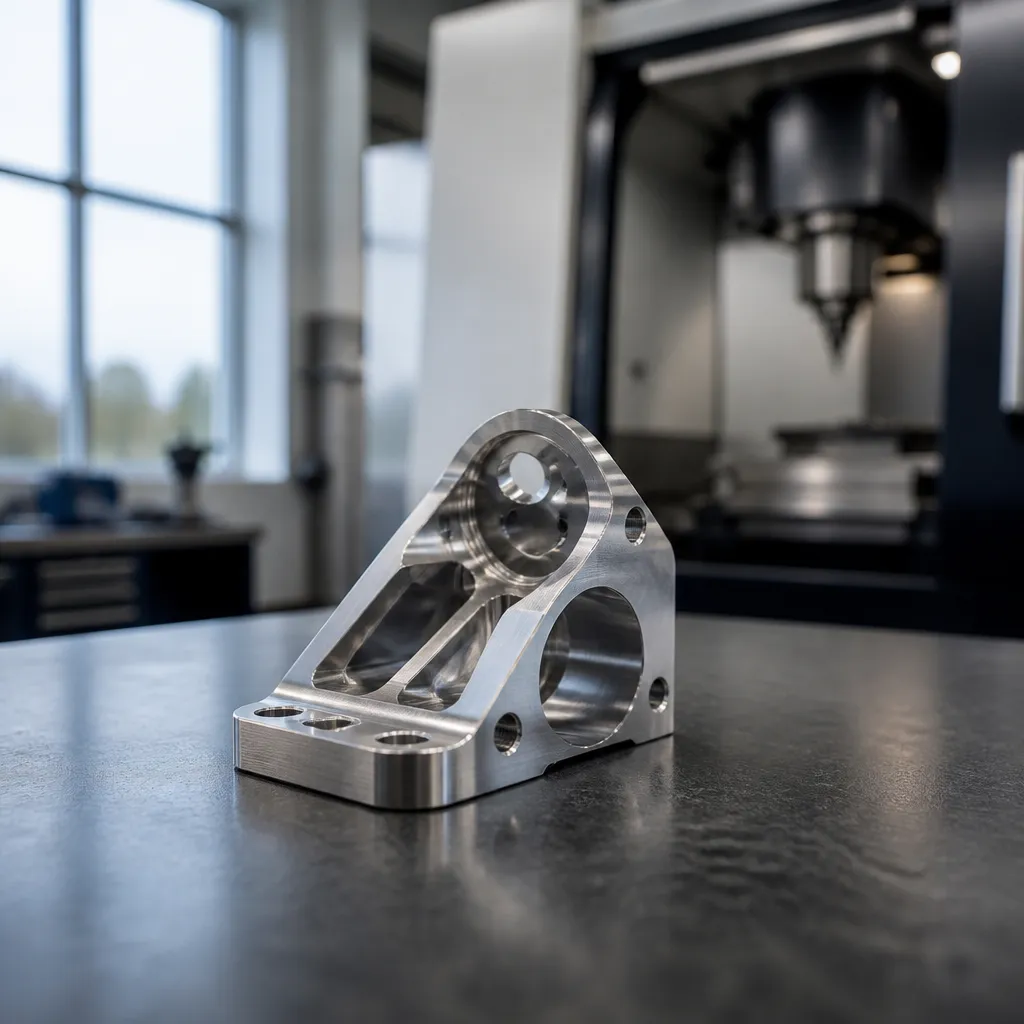
An actuator housing has a different job than a valve body. It locates the actuator to the valve stem, carries the bolt loads, and often contains a bore that a drive shaft turns in for thousands of cycles. The mounting face and bolt pattern decide whether the actuator sits square on the valve, so they deserve as much attention as the internal bore.
Trade coverage of valve and actuator manufacturing has noted that multi-axis machining centers can complete complex actuator housings in a single setup, which reduces handling time and improves quality. That matches what we see on the floor. Every time a housing goes back onto a fixture, the risk of shifting a datum goes up, and the bolt pattern is usually the first feature to show it.

Single-Setup Machining for Housings
When a 5-axis center can reach the mounting face, the drive bore, and the side ports without re-clamping, we machine them that way. The gain is not only speed. Features cut in one setup share a single coordinate system, so bore-to-face perpendicularity is set by the machine's geometry rather than by how well the part seats on a second fixture.
Single-setup work is not always the right answer. If a housing is so large that the fixture blocks tool access, or the volume is too low to justify a dedicated fixture, two setups with a verified transfer are safer. The decision should rest on which datum error you can actually control.
Mounting Pattern Tolerances
Bolt patterns are easy to dimension loosely because each hole looks acceptable on its own. The problem shows up when the actuator is bolted on and the holes are off by a few thousandths in a way that binds the drive shaft. Specify the pattern with true position relative to the drive bore axis, not to the outer edge of the casting.
A practical habit is to run a pin gauge through the bolt pattern before the housing leaves the cell, and to test-fit a mating actuator plate when the customer supplies one. Those checks catch errors that a report can miss when the program measures each hole in isolation.
Choosing a Machining Strategy for Valve Bodies
There is no single best machine for valve bodies. The right strategy depends on part size, port count, bore depth, and how many datum changes the design forces. Our rule of thumb is to choose the setup that keeps the flow centerline and the primary sealing datum in one fixture for as much of the cycle as possible.
Three approaches cover most of the work we see. Each trades something away, and the table below shows where each one fits best. Treat it as a starting point for the quoting conversation, because the print almost always contains details that change the decision.
Approach | Best Fit | Main Limitation |
|---|---|---|
3-axis milling with a rotary or indexing fixture | Mid-volume bodies with a few ports on one or two faces | Each added setup adds a datum transfer risk |
Lathe turning with live tooling | Round bodies and coaxial bores machined from bar stock | Cross ports and off-axis features need extra operations |
5-axis single-setup machining | Complex housings and multi-plane valve bodies | Higher machine cost and more fixture design time |
Lathe-based work suits round bodies where the bores are coaxial with the outside diameter. It is quick for those features but struggles with cross ports unless live tooling is available. Many shops turn the first operations and mill the port work afterward, which is reasonable as long as the transfer datum is controlled tightly.
My direct opinion: if a body has more than two ports on different planes, a fixture-based 3-axis approach is usually a mistake unless the volume is very high and the fixture is dedicated. Datum shifts add up faster than most people expect, and they rarely show up until assembly.
Tolerance Stack-Up and Inspection Strategy
A valve body can meet every individual tolerance and still fail assembly because the stack does not close. A bore position error, a face squareness error, and a seat depth error can each be within print and still add up to a leak path. Inspection has to check the functional relationships, not just a list of isolated dimensions.
Building the CMM Program Around Function
Our CMM programs start from function, not from print order. We measure the flow centerline, then bore positions relative to it, then sealing faces relative to the bores, so the measurement chain follows the way the part will be assembled. Reports organized this way make it clear whether a fit problem is a machining error or a design issue.
Programs should also document the datum scheme. A report that shows a position error without naming the datum it was measured from leaves the receiving engineer unable to tell whether the part or the measurement is at fault.
First Article and Documentation Readiness
First article inspection is where an untested program gets its first real check. We recommend confirming the first article against the functional relationships before committing to a full run, because an error caught on part one costs hours, while the same error caught on part fifty can mean scrapping the lot. Plan documentation such as PPAP packages at the same time, so inspection data supports the submission without rework.
Pro tip: Before the first article goes to inspection, write down the three functional checks the customer cares about most. Set up the CMM routine so those results print first, which shortens the review cycle for everyone involved.
Materials and Thermal Control in Production Runs
Material choice changes how a valve body or housing gets machined. Stainless steels, bronzes, and aluminum castings each cut differently, and the flow path finish, chip control, and tool life all follow from that choice. A process that runs clean on one alloy can smear or burn on another.
Thermal behavior matters as well. Cutting heat can move a part during the cut and again as it cools, which changes bore size and position after the machine has already reported a good result. That is why we treat thermal control as part of the process, not as a problem for the quality team to find later.

Material Choice and Machinability
Harder stainless grades hold a sealing finish well but work-harden if the tool rubs instead of cutting, which is a common cause of broken inserts and poor bore finish. Softer materials such as some bronzes and aluminum castings machine easily but can smear, especially in deep bores. Choose insert geometry and coolant strategy for the material on the print, not for the material you ran last time.
Thermal Drift and Tool Life
Cutting heat changes the tool as well as the part. A dull or overheated tool produces a worse finish and a larger size drift across the run, which can look like a machine problem when the real issue is tool condition. Monitoring tool wear and allowing a stabilization period after long roughing cycles keeps the finishing operations inside the tolerance window.
A practical habit is to measure a witness feature early in each run and again near the end. If the witness moves, the process has a thermal or tool-wear issue, and the fix is usually in the process rather than in the print.
Frequently Asked Questions
What tolerance should a valve body bore have?
It depends on the mating part and the seal design, so the right answer comes from function rather than a general number. In practice, we tighten position on bores that carry stems and seats, and keep diameter tolerance wide enough to machine consistently. Confirm the fit against the seal supplier's requirements and the assembly drawing before setting the callout.
Why do deep valve body bores drift off-axis?
Deep holes drift because the drill follows the path of least resistance, and any runout in the reamer or holder carries that drift forward. The fix is to check straightness before reaming, verify reamer runout at the cutting edge, and use a holder that allows adjustment. Reaming can correct size, but it cannot fully correct a hole that has already wandered.
Is 5-axis machining always better for actuator housings?
No. Five-axis single-setup work reduces datum transfers, which matters most for housings with features on several faces. For a simpler housing with one main mounting face and a bolt pattern, a 3-axis setup on a verified fixture can be quicker to set up and just as accurate.
What finish should flow passages have?
Specify the finish by function and by the toolpath that will produce it. Passages need smooth transitions without steps that create turbulence, and a consistent finishing stepover usually matters more than a single roughness number. Confirm the finish against the customer's flow requirement before locking the process.
What should a first article inspection include for a valve body?
A useful first article checks functional relationships first: flow centerline, bore position relative to that centerline, sealing face squareness and flatness, and the bolt pattern if the body carries an actuator. The report should also name the datum scheme so results can be traced. Hold the full run until those checks pass.
What flow path or fit problem has cost your team the most time on a valve body, and how did you solve it?
References
Overview of CNC machining techniques and considerations for valve body manufacturing
Machinist discussion on deep bore drilling and reaming in valve bodies
Article on automating manufacturing for valve and actuator production


Comments