
Pump and Compressor Component Machining: Tolerance Guide
A pump housing that misses its bearing bore position by a few thousandths rarely fails on the inspection report. It fails on the test stand, or worse, in a customer's chemical plant months later when a seal starts weeping. Pump component machining and compressor part CNC work sit in an unforgiving spot: the parts carry pressure, abrasive or corrosive fluids, and constant vibration, yet most of the drawing does not control performance. Knowing which dimensions govern sealing and alignment, and which ones can relax, is what separates a reliable fluid system from an expensive rebuild. This guide explains how our shop in Fort Wayne approaches those decisions, from tolerance levels and material choice to inspection.
Table of Contents
Quick Takeaways
Key Insight | Explanation |
|---|---|
Tight tolerances belong on function, not the whole drawing | Bores that locate bearings, seal faces, and shaft alignment features earn tight callouts. Envelope dimensions and most mounting features do not. |
Standard shop tolerance is the baseline | Published guidance puts standard production machining at +/-0.005 in. and precision at +/-0.002 in. Start there and tighten only where a mating part demands it. |
Feature locations beat stacked dimensions | Locations held to +/-0.002 in. are reliable when features are machined from the same side. Every re-clamp adds fixturing error. |
Material changes what tolerance is realistic | 316 stainless machines predictably. Duplex grades resist chlorides better but slow cutting and wear tools faster, which affects bore size across a batch. |
Finish on sealing faces matters as much as size | A face that measures in spec but carries the wrong lay or tool marks can still leak. Call out roughness on seal faces, not across the whole housing. |
Inspect the features that fail in service | CMM reports on bores, face runout, and hole positions, tied to the drawing datums, show whether the part will seal and fit. |
Why Pump and Compressor Parts Are Different
A pump housing is a pressure boundary with a machined shape. It holds fluid at line pressure, carries a rotating shaft through bearing bores, and mates with a motor adapter, a seal gland, and piping flanges. A compressor part adds cyclic gas loads, heat, and vibration on top of that. The machining job is to hold the few dimensions that control sealing and alignment, and to leave the rest of the drawing alone.

Most pump and compressor parts start as castings or forgings. CNC machining turns those blanks into functional parts by cutting the bores, faces, ports, and threads that decide whether an assembly seals and runs straight. A guide to CNC machining for industrial pumps and valves makes the same point: blanks are a starting shape, and machining handles the features that set sealing performance, assembly accuracy, and pressure containment.
Pressure Boundaries and Fluid Contact
Any surface wetted by process fluid has to survive that fluid for the life of the pump. Water treatment, chemical dosing, and slurry service each push material choice in a different direction, and the dimensional plan has to follow the material. A housing that machines cleanly in cast iron may need a different bore strategy in stainless if the part will see thermal growth in service.
In practice, we ask the customer three questions before we quote: what fluid the part sees, at what temperature, and whether the fluid carries abrasives. Those answers often decide more about the tolerance strategy than the drawing does.
Why Duty Cycle Changes the Math
A pump that runs continuously wears differently than one that cycles on and off with a level controller. Compressor parts that see repeated pressure reversals show fatigue sooner at sharp corners and poorly finished transitions. That is why the fillet radius and surface finish at those transitions deserve as much attention as the bore diameter.
The most reliable designs are not necessarily the ones with the tightest tolerances. They are the ones where tolerances match what the part has to do in service.
Features That Need Tight Tolerances
Start from the function, not the drawing. A dimension earns a tight callout when a mating part depends on it, when a seal depends on it, or when it sets the alignment of a rotating element. Everything else should carry a looser general tolerance, because each tight dimension adds inspection time, fixturing effort, and scrap risk.
On pump and compressor work, the features that consistently justify tight control fall into three groups. Each one connects to a failure mode that shows up in the field if it is left loose.
Bearing Bores and Shaft Alignment
The bearing bore sets the radial location of the shaft. If the bore is off in size, the bearing either spins in the housing or gets crushed. If it is off in position or concentricity relative to the seal bore, the shaft runs off-center, and the seal sees a wobble it was never designed to handle. Bore diameter and bore location to the datum are usually the two dimensions to call out tightly.
Seal Bores and Gland Faces
Seal bores and gland faces are where most leakage starts. The bore diameter must match the seal's stated fit, and the face the seal rides on must be square to the shaft axis within a tolerance the seal manufacturer can accept. Runout measured on a CMM or with a dial indicator tells you more than a single diameter callout ever will.
Port Positions and Flange Patterns
Port positions and bolt-hole patterns are where tolerance stacks show up in the field. A flange pattern that is off by a few thousandths will not bolt up cleanly, so the installer forces it, and that puts stress on the housing. Feature-to-feature location tolerances controlled from one datum are the right tool here, not a string of individual plus-minus dimensions.
Pro tip: Before accepting a tight callout on a bore, ask which mating part controls the fit. The bearing or seal supplier's published fit usually governs, and the number in their catalog is the one to copy, not the number a template suggests.
Tolerance Levels in Practice
Most shops work in three practical tiers, and it helps to know where each one sits before you send a drawing out for quotes. Published guidance from one CNC prototype and production provider puts its standard machining tolerance at +/-0.005 in. (0.13 mm), with a precision tier at +/-0.002 in. (0.051 mm). Those numbers are a reasonable baseline for general features on pump housings, but they are not a target for every dimension.
Unspecified dimensions usually fall under a general tolerance standard such as ISO 2768, which many drawings call out in the title block. That default catches most of the drawing, so the callouts you add by hand should be deliberate. A drawing that puts a tight tolerance on every dimension is not more accurate. It is more expensive, and the extra cost rarely buys anything on a pump.
Standard, Precision, and Reamed Hole Callouts
Reamed holes for dowel pins and locating features can be held much tighter than general bores. The same guidance cites +/-0.0005 in. (0.0127 mm) on reamed holes, which is why dowel holes are usually where you spend your tolerance budget. Some machine shops advertise tighter capability on specific features, but that capability depends on geometry and setup. It is not a default for every part.
The practical rule is simple. Put precision on the one or two holes that locate assembly, and let the rest of the part run at the standard tier.
Feature Location Versus Single Dimension
A single dimension can be held tightly, but the distance between two features machined in separate setups is where error accumulates. The same published guidance notes +/-0.002 in. (0.051 mm) on feature locations, provided those features are machined on the same side of the part. That condition matters, because every re-clamp adds a fixturing error that no amount of spindle precision removes.
When Geometric Dimensioning Makes Sense
Geometric dimensioning and tolerancing, defined under the ASME Y14.5 standard, describes form, orientation, location, and runout relative to datums. Plus-minus callouts cannot express a true position requirement for a bolt pattern, which is why it shows up on well-made pump drawings. If a bolt pattern is controlled by two separate plus-minus dimensions, the drawing is probably under-specified and the assembly will eventually argue with you.
Material Choice and Machinability
Material decides what tolerance is realistic. A tight bore in a stable, free-machining alloy holds size easily. The same bore in a tougher stainless may need a different tool path, more finish passes, and tighter tool management to hold the same number. Check material behavior with your machinist before you finalize the tolerance table.
Industrial pump and valve guides consistently list 316 stainless steel among the most common materials, because it balances corrosion resistance with machinability. It is a reasonable default for many water and chemical service applications. Duplex stainless offers stronger resistance to chloride corrosion, but it costs more to machine and wears cutting tools faster. Choose duplex because the media demands it, not because it sounds more durable.

316 Stainless as the Balanced Default
For many water, chemical, and general process pumps, 316 machines predictably and holds dimensions through a production run. It work hardens to a moderate degree, so sharp tools and steady feeds matter. A bore in 316 that drifts out of size after a tool wears is almost always a process problem, not a material failure, and the fix is a tool change interval you can defend.
Duplex Grades and Tool Wear
Duplex grades are tougher to cut, and they push tools to wear faster, which affects both tolerance and cost. Tool wear shows up as bore taper or size drift across a batch. We plan duplex jobs with more frequent tool checks, and we treat the first pieces as process confirmation before the run starts. Customers who ask for tight bores in duplex should expect a longer cycle, not just a higher material price.
Cast Blanks and Machining Allowance
Castings bring their own variation in wall thickness and stock. If the machining allowance is thin in one area, the bore may break through or leave an uneven cut. Specifying a consistent allowance on the casting drawing is one of the cheapest ways to protect a tight tolerance later in the process.
Surface Finish and Sealing Faces
A sealing face can be dimensionally perfect and still leak. Tool marks, feed lines, and the wrong lay direction create small channels that a gasket or mechanical seal cannot close. Surface finish is part of the tolerance story, even though it often appears as a separate line on the drawing.
Published guidance on industrial pumps and valves makes the same point: surface finish can directly affect sealing performance and equipment life. Our rule is to call out finish only on sealing faces, bearing journals, and surfaces that carry a load. Specifying a fine finish across the whole housing adds cost without improving function.
Specifying Roughness on Seal Faces Only
Give the seal face its own finish callout and keep it separate from the general finish note. Ask the seal supplier what finish and lay direction they recommend, because some designs call for a specific pattern to hold a fluid film. Measuring that finish with a profilometer at inspection gives you a traceable number instead of an opinion.
Turned Versus Milled Faces
Faces produced by turning and faces produced by milling can both meet a callout, but they leave different textures. Turned faces often give a more consistent circular lay, which suits some seal designs well. Milled faces with a clean finishing pass can perform just as well, but the lay direction must be controlled deliberately. We settle this choice with the customer before the first part is cut, not after a failed leak test.
Choosing a Machining Approach
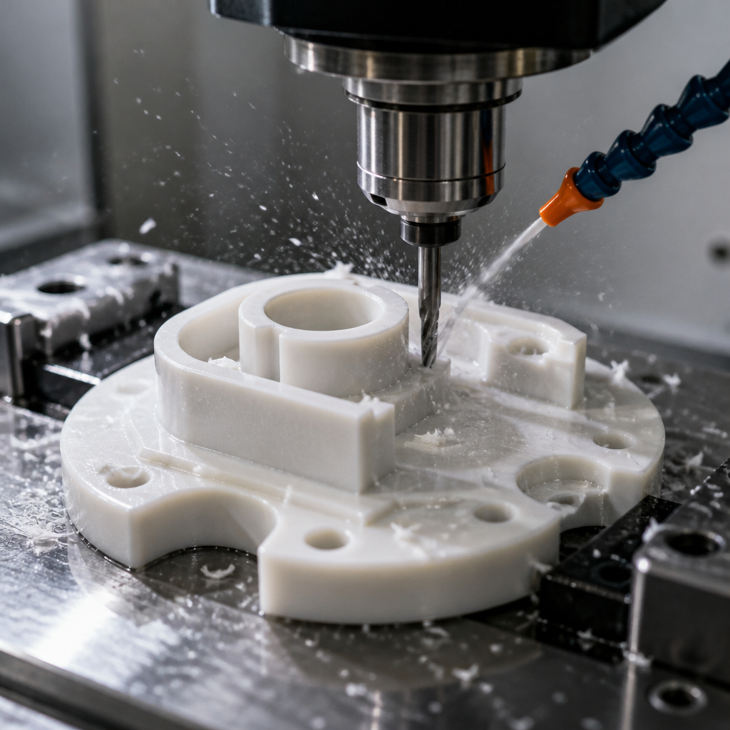
Machine choice affects tolerance more than many engineers expect. A part with features on five faces holds location better in a single 5-axis setup than in three separate operations, because the datum does not move between operations. Turning, milling, and wire EDM each have a role, and most pump and compressor parts need at least two of them.
5-axis machining brings the cutting tool to more faces without repositioning, which reduces stacked error on angled ports and complex housings. Industry overviews of 5-axis CNC machining point to fewer repositioning steps and better access to difficult features as the main advantages. Those benefits are real, but they depend on good fixturing and a careful program.
Approach | Best Fit for Pump and Compressor Parts | Main Limitation |
|---|---|---|
5-axis CNC milling | Housings with angled ports, multi-face bores, and flange patterns that must share one datum | Higher programming and fixture cost, and it is wasteful on simple round parts |
CNC turning on a lathe | Shafts, impeller hubs, bushings, and concentric bores on round parts | Limited for prismatic housings with features spread across several faces |
Wire EDM | Hardened internal profiles, sharp internal corners, and small features a cutter cannot reach | Slow for most pump work, and it can leave a recast layer that needs finishing |
Fewer Setups Means Fewer Stacked Errors
Every setup change introduces a new reference and a new chance for error. When we quote a housing, we count setups first and tolerance second, because a part that needs four setups for a bore, two flanges, and a port cluster will struggle to hold its location callouts. Consolidating operations is often the most effective tolerance improvement we can offer, and it usually lowers cost too.
Where Wire EDM Earns Its Cost
Wire EDM is the right tool when a feature is too hard to cut efficiently or too deep for a standard end mill. It is not a shortcut for loose drawings. Use it for the specific internal profile that justifies it, and let milling or turning handle the rest of the part. Adding a finishing pass after EDM is common, and the quote should reflect it.
Inspection and Documentation
A tolerance that nobody measures is a wish. Inspection turns the drawing into evidence, and for pump and compressor parts that evidence should cover bores, faces, runout, and hole locations, not a random sample of diameters. CMM reports are the most useful record because they show where the part sits relative to its datums, not only whether individual dimensions passed.
Our shop is A2LA accredited, and we run first article inspection and PPAP documentation for customers who need a formal package before production release. Calibration support through our MetroLab division keeps measuring equipment traceable, which matters when a customer questions a result months after shipment.

First Article Inspection on Housings
On a first article, measure every toleranced feature and record it on the report, including reamed holes and seal bore runout. The first article is where you learn whether the fixture and program hold the callouts. If a dimension fails on the first piece, fix the process before the run, because the cost of rework grows with every part that follows.
CMM Programs That Check the Right Features
A CMM program for a pump housing should probe datums in the order the drawing defines them, then check bores, faces, and hole positions against those datums. Programs that measure features in a convenient order rather than the drawing order produce reports that look clean and say little. We build the program from the drawing, then review it with the machinist before the first measurement.
Common Tolerance Mistakes
Most tolerance problems we see come from drawings that are either too loose on critical features or too tight everywhere. Both are avoidable. The mistakes below show up on incoming drawings often enough that we check for them on every quote.
One machining guide we reviewed reports that design-for-manufacturing practices can cut machining costs by 20 to 30 percent without affecting function. Most of that saving comes from loosening tolerances nobody needed and simplifying features that do not affect sealing or alignment.
Tolerancing Every Dimension Tight
A drawing with tight tolerances on every dimension forces secondary grinding or EDM operations that add lead time. As one published tolerance guide warns, an overly stringent tolerance can send parts to a secondary operation, unnecessarily increasing cost and lead time. Tighten the features that seal and align, and let the rest of the part run at the standard tier.
Ignoring Mating Part Tolerances
A housing tolerance means little if the impeller or bearing it mates with carries a different tolerance. Callouts that are too loose, or that do not line up with the mating parts, can make assembly impossible or force rework. Check the mating drawing before you set the housing bore, and keep both drawings under the same revision.
Forgetting Thermal and Fixturing Effects
Parts that run hot in service grow, and parts clamped too hard in a fixture distort when released. Both change the size and roundness of a bore. Ask whether the part will run well above room temperature, and check the bore after clamping and release, not only on the bench.
Pro tip: Send the drawing back to the designer with one question: which three dimensions would cause a field failure if they were 0.005 in. off? The answer is usually short, and the rest of the drawing can relax.
Frequently Asked Questions
What tolerance should a pump housing bore have?
There is no single answer, because the right value depends on the bearing or seal fit, not the housing alone. Start with the supplier's published fit for the bearing or seal, then apply a tolerance tight enough to hold that fit across the production run. For general features, standard machining tolerance is a reasonable starting point.
Why do pump parts need feature location tolerances instead of single dimensions?
Bolt patterns and port positions must line up with mating parts. Two plus-minus dimensions measured from different setups can stack up beyond what the assembly can accept. A location tolerance from a single datum, machined from one side where possible, gives you a controlled relationship between features.
Is 316 stainless always the right material for pump components?
No. 316 is a sensible default for many water and general process applications because it balances corrosion resistance and machinability. Harsher chloride environments may call for a duplex grade, but duplex costs more to machine and needs closer tool management. Choose the material based on the fluid and temperature, then set the tolerances.
When should a machine shop use wire EDM instead of milling?
Use wire EDM when a feature is hard to reach with a cutter, when the material is too hard to cut efficiently, or when you need sharp internal corners. It is slower than milling for most pump work and can leave a recast layer that needs finishing. Reserve it for the features that justify it, not entire housings.
What documentation should I ask for when buying machined pump or compressor parts?
Ask for a first article inspection report that shows every toleranced feature, CMM reports for critical bores and hole positions on production lots, and material certification. If your customer requires formal approval, request PPAP documentation. Calibration records for the measuring equipment make the reports defensible when questions come up later.
If you have run into a pump or compressor part where a tolerance callout caused a field failure or a surprise invoice, share what happened and what you changed, because those experiences shape how we quote the next job.


Comments