
GD&T Machining: Multi-Surface Components Guide
Most tolerance-related rejections in precision machining do not happen because a shop cannot hold a dimension. They happen because the drawing never clearly communicated what that dimension was supposed to control. GD&T machining is the discipline that closes that gap, and for multi-surface components it is not optional. When a part has five or six datum references, compound angles, and features that must relate to each other across multiple faces, a coordinate-based callout on a 2D drawing will fail the production team before the first chip is cut. At SCPM, this is the class of problem we see most often from customers coming off a bad run with a previous shop.
Table of Contents
Quick Takeaways
Key Insight
Explanation
GD&T is a symbolic language, not a shorthand
ASME Y14.5 defines exact rules for how each symbol is interpreted. A profile callout and a positional callout are not interchangeable, even when they look similar on a drawing.
Datum selection drives everything downstream
The wrong primary datum on a multi-surface component means your machining setup and your inspection setup will never agree, producing false rejects or missed defects.
Tighter tolerances are not always better
Unnecessarily tight geometric tolerances increase cycle time, tool wear, and part cost with no functional benefit. Specify only what the part must do.
Tolerance stack-up is a systems problem
Individual features can be within spec while the assembled component fails. Stack-up analysis must happen at the design stage, not during PPAP.
Profile of a surface is the most powerful GD&T control
For multi-surface components, profile of a surface controls size, form, orientation, and location in a single callout. It simplifies inspection and eliminates ambiguity.
CMM programming must mirror the drawing's datum reference frame
If the CMM alignment routine does not replicate the functional datum scheme shown on the drawing, measurement results are mathematically valid but physically meaningless.
PPAP documentation requires complete GD&T traceability
Every balloon on a PPAP drawing must link to a measured result. Missing or ambiguous GD&T callouts create gaps in first article inspection reports that customers reject.
What GD&T Machining Actually Means for Multi-Surface Parts
Geometric Dimensioning and Tolerancing (GD&T) is a symbolic language used on engineering drawings and 3D models to define the nominal geometry of a part and the permissible variation of its features. The governing standard in the United States is ASME Y14.5, which provides a comprehensive set of rules for interpreting every symbol, modifier, and datum reference frame used in the system.
For single-feature parts, the difference between a coordinate tolerance and a GD&T callout is mostly academic. For multi-surface components, it is the difference between a part that assembles reliably and one that produces warranty returns. When a machined component has bores on three faces, a slot that must align to a compound angle, and a sealing surface that must be flat to a few microns, coordinate tolerances produce an interpretation problem. Each shop reads the drawing differently. Each inspector measures from a different origin.
GD&T resolves this by establishing a datum reference frame that everyone, the designer, the machinist, and the CMM programmer, works from identically. The datum reference frame is not just a measurement convention. It is a functional model of how the part sits in its assembly.


Pro tip: When you receive a drawing with mixed tolerancing schemes, where some features use GD&T and others use coordinate plus-minus tolerances, treat the boundary between those two systems as your highest risk area. Features that span that boundary are frequently under-constrained.
Geometric Tolerancing Fundamentals Every Machining Engineer Must Know
GD&T controls fall into five categories: form, orientation, location, runout, and profile. Each category targets a different type of geometric error. Knowing which category applies to a given functional requirement is the core skill that separates engineers who write good drawings from those who create expensive inspection disputes.
Form Controls and Why They Carry No Datum
Flatness, circularity, cylindricity, and straightness are form controls. They describe the shape of a single surface or feature in isolation. Critically, form controls carry no datum reference because they do not describe how that feature relates to anything else on the part. A flatness callout of 0.005 inches on a sealing face means that face must fit within two parallel planes separated by 0.005 inches, regardless of where on the part that face sits.
A common mistake is applying a flatness callout when the functional requirement is actually parallelism to a datum surface. Parallelism is an orientation control. It controls both flatness and angular relationship to a datum simultaneously. Using flatness when you need parallelism results in a part that passes inspection but fails in the assembly because the two mating surfaces are parallel to each other but not to the reference structure.
Profile of a Surface for Multi-Surface Components
Profile of a surface is the most capable single GD&T control available for complex machined geometry. It defines a tolerance zone that wraps uniformly around the true profile of a surface, controlling size, form, orientation, and location simultaneously when datum references are included.
For a five-axis milled component with compound-angle surfaces and blended radii, profile of a surface is frequently the only practical callout. Trying to describe the same requirements using individual flatness, angularity, and position controls produces a drawing so dense with feature control frames that it becomes unreadable. Profile simplifies both the drawing and the inspection plan.
The single most common source of machining cost overruns on multi-surface components is a drawing that uses the wrong GD&T control type for the functional requirement, forcing the shop to either over-inspect or re-negotiate the tolerance after the first article fails.
Datum Structure and Multi-Surface Component Machining
Datum selection is the first decision on a multi-surface component drawing, and it is the one that cannot easily be corrected later. The datum reference frame defines which surfaces are the primary, secondary, and tertiary datums, which determines how the part is constrained in six degrees of freedom during both machining and inspection.
Matching Datums to Functional Assembly Surfaces
The most reliable rule in practice: datums must correspond to functional surfaces, meaning the surfaces that actually contact the mating assembly. If the part bolts down on a flat face and locates on two pins, that flat face is Datum A and the pin holes drive Datums B and C. This is not a suggestion. When datums do not match assembly interfaces, the part can be within every GD&T tolerance and still fail to assemble correctly.
For multi-surface components machined on a 5-axis CNC platform, the datum structure on the drawing must also be achievable in the machining fixture. If the primary datum is a surface that the fixture cannot contact without blocking tool access to other features, the setup engineer will improvise, and the improvised datum will not match the drawing. At that point, inspection results and functional performance diverge.
Datum Shift and Maximum Material Condition
The Maximum Material Condition (MMC) modifier applied to a datum feature introduces datum shift, an additional tolerance that is available when the datum feature departs from its maximum material size. This is valuable in high-volume production because it allows more parts to pass inspection without being reworked. However, it requires that the shop and the inspection team both understand when and how much shift is available. Misapplying MMC on a datum reference is one of the fastest ways to produce an inspection report that no one can interpret consistently.
Pro tip: On multi-surface components where the same datum scheme controls features on three or more faces, build a datum precedence table into your drawing notes. List Datum A, B, and C with a brief functional description of each. It takes five minutes to add and saves hours of interpretation calls during first article inspection.
Tolerance Stack-Up: The Real Cause of Assembly Failures
Tolerance stack-up occurs when multiple toleranced features in an assembly accumulate, meaning their individual variations combine in a way that can cause the assembly to fail even when every single part is within its specified tolerance. This is not a theoretical concern. It is the most common cause of production-line fit failures in precision assemblies.
For multi-surface components, the stack-up problem is compounded because a single part can contribute variation from several faces simultaneously. A housing that locates a bearing on one face, seals against a gasket on a second face, and bolts to a structure through a third face can accumulate position error, flatness error, and perpendicularity error across all three interfaces in ways that interact unpredictably.
Worst-Case vs. Statistical Stack-Up Analysis
Worst-case stack-up analysis calculates the maximum possible accumulated error by adding the worst-case tolerance contribution from every part in the loop. It guarantees that if every part is within spec, the assembly will work. However, it often forces tighter individual tolerances than necessary, driving cost up.
Statistical stack-up analysis (root sum square or Monte Carlo) uses the probability distribution of each tolerance to estimate likely assembly outcomes. It allows looser individual tolerances while maintaining acceptable assembly yield. The correct approach depends on production volume and the consequence of an assembly failure. For safety-critical parts, worst-case is non-negotiable. For high-volume commercial assemblies, statistical methods often justify significantly relaxed tolerances.
The key point is that stack-up analysis must happen before drawings are released, not during PPAP. Discovering a stack-up problem at first article inspection means the tolerances on already-designed parts must be tightened, which may require a new machining process, new fixturing, or a fundamental design revision.
Comparing GD&T Control Types for Complex Machined Features
Choosing the right GD&T control type for a given feature is one of the most consequential decisions in drawing preparation. The table below compares three commonly applied controls on multi-surface machined components.
GD&T Control Type
What It Controls
Best Application on Multi-Surface Components
True Position (Location)
Location of a feature's axis or center plane relative to a datum reference frame. Controls where the feature is, not its shape.
Bolt hole patterns, pin locations, bore centers that must align across mating parts. Most effective when MMC or LMC bonus tolerance is functionally appropriate.
Profile of a Surface
Size, form, orientation, and location of any surface simultaneously, when datum references are included in the callout.
Compound-angle milled surfaces, blended contours from 5-axis operations, and any surface where multiple geometric characteristics must be controlled in a single unified tolerance zone.
Perpendicularity / Angularity (Orientation)
Angular relationship of a surface or axis to a datum. Does not control location of the feature, only its orientation.
Bores on secondary faces that must be square to the primary datum, mounting pads that must be at a specific angle to a reference plane. Use when location is already controlled by another callout.
In practice, a well-constructed drawing for a multi-surface component uses all three control types together. Position locates the features. Profile controls the surface geometry. Orientation controls angular relationships that position and profile do not fully capture. The mistake most engineers make is trying to use one control type for every requirement, either over-constraining the part or leaving geometric errors unchecked.
Inspection and CMM Programming for GD&T-Defined Parts
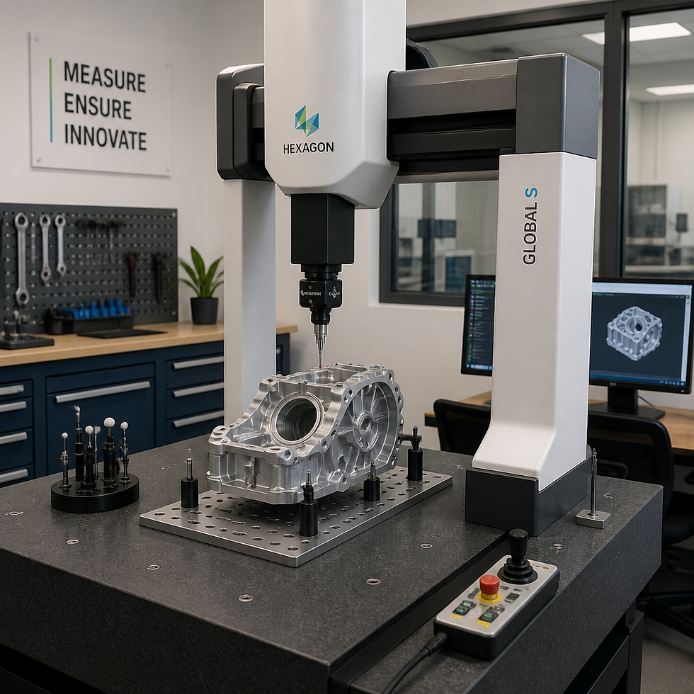
A GD&T drawing is only as useful as the inspection plan that implements it. For multi-surface components, that inspection plan is a CMM program, and the CMM program must be written to replicate the datum reference frame shown on the drawing. This sounds obvious. In practice, it is frequently where the interpretation breaks down.
We would love your feedback and any insights you would share with others. What perspective would you add?
Replicating the Datum Reference Frame in CMM Alignment
The CMM alignment routine is the mathematical equivalent of seating the part in its functional assembly. Datum A constrains the part in one degree of freedom (rotation about its plane normal and translation along it). Datum B constrains two more. Datum C constrains the final two. If the CMM alignment routine contacts the wrong surfaces or contacts the correct surfaces in the wrong order, the entire measurement is referenced to a different coordinate system than the drawing specifies.
The output will look valid. Numbers will appear. Reports will print. But none of the reported values will correspond to what the drawing actually requires, and a part that passes CMM inspection may fail in the assembly, or vice versa. This is not an edge case. At SCPM's MetroLab, we regularly see incoming inspection failures that trace directly to a misaligned datum scheme in the sending shop's CMM program.
First Article Inspection and PPAP Traceability
PPAP documentation requires that every characteristic on the drawing is measured and reported with a result that is traceable to the callout. For GD&T-controlled features, this means the inspection report must identify the specific GD&T control (flatness, position, profile, etc.), the nominal value, the tolerance, the actual measured value, and the pass or fail status. Missing any of these elements for any balloon on the drawing produces an incomplete PPAP that customers with ISO 9001 or IATF 16949 quality systems will reject.
Customers who bring first article work to SCPM frequently arrive with partial inspection data from a previous supplier where the CMM operator measured dimensions but did not document which GD&T control each measurement satisfied. Reconstructing that traceability from undocumented measurement data is time-consuming and often impossible without remeasuring the parts from scratch.
Common Drawing Mistakes That Drive Up Machining Cost
After reviewing drawings across a wide range of industrial customers, the same categories of errors appear repeatedly. None of them are the result of carelessness. They are the result of designers who understand design intent but have not worked closely enough with the machining and inspection process to anticipate how the drawing will be read on the shop floor.
Applying Tight Tolerances Globally Instead of Functionally
ISO 2768 defines four grades of general machining tolerances (f, m, c, and v) for linear and angular dimensions when no specific tolerance is stated. Engineers who are not familiar with this standard sometimes apply very tight title block tolerances globally, specifying plus-or-minus 0.001 inches as the default for an entire drawing. This forces the shop to treat every unmachined edge, every clearance hole, and every cosmetic chamfer as a precision feature. Cycle times increase. Inspection time increases. Scrap rates increase. None of these costs produce any functional benefit.
The correct approach is a permissive general tolerance (ISO 2768-m or an equivalent) for non-functional features, with specific GD&T callouts applied precisely where the part's function actually requires controlled geometry.
Redundant or Conflicting Tolerances on the Same Feature
A feature that has both a coordinate plus-minus location tolerance and a GD&T true position callout is over-defined. The two controls will produce different pass-fail results for the same measured part. Inspectors and machinists will default to whichever control is easier to check, which may not be the one that actually matters. On a multi-surface component with dozens of features, even a few redundant callouts can make the drawing unworkable.
Before releasing any drawing for a multi-surface component, run a control audit: list every feature, identify every tolerance that applies to it, and confirm that no feature has conflicting or redundant controls. This takes time during design. It saves far more time during production.
Ignoring the Measurement Uncertainty Contribution
Any tolerance tighter than roughly four to ten times the measurement system's uncertainty becomes difficult to inspect reliably. For very tight GD&T callouts on surfaces that require CMM measurement, the uncertainty of the CMM probe, the fixture repeatability, and the part temperature all contribute to the measurement result. A callout of 0.0002 inches on a part that will be measured on a CMM with a 0.0001-inch uncertainty budget is asking the inspection system to deliver more information than it can reliably provide. Customers who call SCPM to discuss tight-tolerance components should expect this conversation before quoting, not after the first article.
Frequently Asked Questions
What is the difference between GD&T and coordinate tolerancing for machined parts?
Coordinate tolerancing uses plus-minus values on individual dimensions to define acceptable variation in X, Y, and Z independently. GD&T uses a symbolic language defined by ASME Y14.5 to control form, orientation, location, and profile of features relative to a defined datum reference frame. For simple parts, the practical difference is small. For multi-surface components, coordinate tolerancing creates ambiguity in how the part is oriented during inspection and how feature relationships are evaluated. GD&T eliminates that ambiguity by making the datum reference frame and the tolerance zone geometry explicit.
How does 5-axis CNC machining interact with GD&T datum structure?
Five-axis CNC machining allows a part to be fixtured once and machined on multiple faces without re-fixturing. This is a major advantage for multi-surface components because re-fixturing introduces datum shift errors between setups. However, the 5-axis setup must be aligned to the same datum reference frame shown on the drawing. If the drawing's primary datum is a face that the fixture obscures, the setup engineer will use a surrogate datum, and any GD&T callouts that reference the primary datum will be measured from a different origin than they were machined from.
When should profile of a surface be used instead of true position?
Use true position when you need to control the location of a feature's axis or center plane, such as a hole pattern or a pin. Use profile of a surface when you need to control the geometry of a non-cylindrical surface, a compound-angle face, a blended contour, or any surface where size, form, orientation, and location all matter simultaneously. Profile is more comprehensive but also more demanding to inspect, because it requires a CMM to sample enough points across the surface to characterize the entire profile, not just a single axis location.
What causes tolerance stack-up failures in precision assemblies?
Tolerance stack-up failures occur when the individual dimensional variations of multiple parts in an assembly combine in a way that pushes the assembled dimension outside its functional limit, even when each part is within its own specified tolerance. On multi-surface components, this happens most often when location tolerances on features across different faces accumulate without a stack-up analysis being done at the design stage. The fix is to analyze the worst-case or statistical accumulation of tolerances along every critical assembly loop before finalizing drawings.
How does A2LA accreditation affect GD&T inspection and PPAP documentation?
A2LA accreditation means that a laboratory's measurement processes have been independently assessed against internationally recognized standards for measurement traceability, uncertainty estimation, and quality system controls. For GD&T inspection and PPAP documentation, accreditation means the CMM measurements, calibration records, and inspection procedures used to support the first article inspection report are backed by a verified quality system. Customers in automotive and aerospace supply chains frequently require accredited inspection results for PPAP submissions to meet their own quality management obligations.
Can geometric tolerancing requirements be applied retroactively to legacy drawings?
Technically yes, but it requires careful validation. Converting a legacy coordinate-toleranced drawing to GD&T is not a simple transcription exercise. The conversion must establish a datum reference frame that reflects actual functional assembly interfaces, which may not be obvious from the original drawing. Features that were implicitly constrained by coordinate dimensions may need explicit GD&T orientation or location controls. Any retroactive conversion should be validated against the assembly requirements before the revised drawing is released for production, and first article inspection should be repeated against the new callouts.
If you are working through a GD&T machining challenge on a multi-surface component, whether at the drawing review stage, first article, or somewhere in the middle of a production run that is not going as planned, share your specific situation in the comments below. The specifics of what is failing and why matter far more than the general principles, and practical experience with your part geometry is usually where the most useful answers come from.


Comments