
Custom Gauge Manufacturing: Repeatability & GR&R Guide
Most measurement problems on the production floor are not operator problems. They are gauge problems. When a custom inspection tool is specified poorly, it introduces variation that no amount of operator training can eliminate. The result shows up in your Gauge R&R study as a failing score, in your PPAP package as a red flag, and eventually in scrap, rework, and customer escapes. This guide walks through exactly how to specify custom gauge manufacturing for repeatability, and what you need to lock down before a single detail drawing gets issued so your measurement system passes GR&R on the first attempt.
Table of Contents
Quick Takeaways
Key Insight
Explanation
GR&R under 10% is the hard target
Per AIAG MSA guidelines, a total Gauge R&R below 10% of study variation is considered acceptable. Between 10% and 30% is marginal and requires justification. Over 30% is a failing measurement system.
Gauge resolution must be at least 1/10 of part tolerance
If your tolerance band is 0.010 inches, your gauge must resolve to at least 0.001 inches. Coarser resolution artificially inflates repeatability error and will sink a GR&R study.
Datum selection is not a gauge question, it is a design question
The datum scheme on your gauge must mirror the datum scheme in your engineering drawing. Mismatched datums produce repeatable errors that look like part variation but are actually fixturing variation.
Attribute gauges pass GR&R differently than variable gauges
Go/no-go gauges use an attribute GR&R method. Variable gauges use the ANOVA or average-and-range method. Specifying the wrong type for your application changes how compliance is demonstrated.
Gauge tolerance should be 10% of part tolerance maximum
A commonly applied gaugemaker’s rule sets the gauge manufacturing tolerance at 10% of the part tolerance it checks. Tighter is always better, but violating this rule guarantees measurement uncertainty problems.
Temperature and surface finish affect gauge performance after delivery
A gauge that passes GR&R in a climate-controlled metrology lab can fail on a shop floor that swings 20 degrees Fahrenheit. Specify material and environment requirements at the design stage.
Custom gauges must be calibrated to a traceable standard
Calibration to NIST-traceable standards is required for any gauge used in regulated inspection. An A2LA-accredited lab can issue calibration certificates that satisfy automotive and aerospace customer requirements.
Why Custom Gauge Design Drives GR&R Outcomes
A GR&R study is a structured experiment that separates total measurement variation into two sources: repeatability (the gauge's ability to return the same reading on the same part under the same conditions) and reproducibility (the variation introduced when different operators use the same gauge). Most manufacturers focus their corrective action on operator training. That is the wrong place to start.
When a gauge has poor geometry, inadequate locating features, or insufficient resolution, repeatability error is high regardless of how skilled the operator is. The gauge itself is the limiting factor. Getting repeatability right is purely a function of how well the inspection tool was designed and manufactured, which is why custom gauge manufacturing investments pay off directly in GR&R scores.
In practice, the most common design failures that sink a GR&R study are: contact point geometry that allows the gauge to rock on the part surface, locating datums that do not match the drawing, resolution that is too coarse for the tolerance being checked, and thermal expansion mismatches between the gauge material and the part material. Every one of these is a specification problem, not an operator problem.
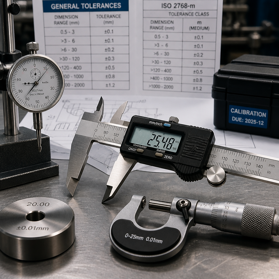

GR&R Acceptance Thresholds: What the Numbers Mean
The AIAG Measurement System Analysis (MSA) reference manual establishes the thresholds that virtually every automotive and aerospace customer references. A total GR&R result below 10% is acceptable. Results between 10% and 30% require customer review and may be conditionally accepted based on the criticality of the characteristic and the cost of improving the measurement system. Results above 30% indicate the measurement system is not capable and parts should not be dispositioning based on it.
The percentage is calculated against either total study variation or the part tolerance, depending on the context. Percent tolerance, sometimes called P/T ratio, evaluates the gauge's variation as a fraction of the engineering tolerance. This is the most practically meaningful number because it tells you directly how much of your tolerance band is being consumed by measurement uncertainty.
When the raw repeatability of a gauge equals 3% of the total tolerance bandwidth, the measurement system will typically produce a GR&R of approximately 10%. Acceptable GR&R requires gauges built tight enough to stay well below that boundary.
The discrimination ratio is the other number that gets overlooked. AIAG guidance generally requires a gauge to have at least five distinct categories of discrimination, meaning it must be sensitive enough to tell apart at least five meaningfully different levels of part variation within the tolerance band. A gauge that cannot meet this threshold is not a precision instrument, it is a sorting device at best.
Pro tip: Run a preliminary resolution check before ordering a custom gauge. Calculate one-tenth of your tightest feature tolerance. That is the minimum resolution your gauge needs to display. If a commercially available instrument meets that threshold and can be fixtured to your part geometry, a fully custom solution may not be required. If it cannot, custom gauge manufacturing is the correct path.
Specifying a Custom Gauge: The Inputs That Matter
Most gauge failures start not at the machine but at the specification stage. The gauge manufacturer needs complete information to build a tool that performs in your environment, not just in the design office. Treating the gauge specification as a simplified version of your part drawing is a common and costly mistake.
Part Tolerance and Feature Geometry
Provide the actual engineering tolerance for every feature the gauge will check. Do not round. Do not provide "working tolerances." If a bore diameter has a tolerance of plus 0.0008 inches and minus zero, the gauge specification must reflect that asymmetry exactly. Symmetric gauges built for asymmetric tolerances systematically miscall borderline parts.
Include surface finish callouts for every contact surface. A gauge contact point pressing against a ground surface behaves differently from one pressing against a turned or milled surface. The contact geometry, whether a sphere, a flat, or a knife edge, must match the workpiece geometry to achieve consistent seating.
Production Environment and Material Compatibility
Specify where the gauge will live. A floor gauge that sees coolant, chips, and temperature swings from 60 to 90 degrees Fahrenheit needs sealing, drainage paths, and a material matched to the thermal expansion behavior of the part. A gauge that checks aluminum parts should ideally be made from a material with a similar coefficient of thermal expansion, or it should be used only in a temperature-controlled environment. A common mistake is specifying a hardened steel gauge for an aluminum part without accounting for differential thermal growth. At 10 degrees Fahrenheit of temperature difference, the error can exceed the tolerance on close-work features.
Gaugemaker's Tolerance
The gauge itself must be manufactured to a tolerance. The standard rule of thumb is that the gauge manufacturing tolerance should not exceed 10% of the part feature tolerance it is intended to check. This is sometimes called the gaugemaker's rule. For very tight tolerances, achieving a 10% gauge tolerance may push into the capabilities of specialized toolroom grinding and precision metrology, which is exactly where an experienced custom gauge manufacturer adds value over a general job shop.
Gauge Types and When to Use Each
Selecting the right gauge type for your inspection requirement is as important as the manufacturing quality of the tool. The wrong category of gauge introduces systematic errors that no amount of precision manufacture can correct.
Go/No-Go Plug and Ring Gauges
These are attribute gauges. They produce a pass or fail result, not a measurement value. They are fast, difficult to misread, and ideal for high-volume production where the goal is to confirm a part is within tolerance, not to measure how far within tolerance it sits. Their GR&R is evaluated using attribute methods, not variable methods. The gauge tolerance is built directly into the gauge geometry, making the gaugemaker's tolerance allocation critical. Plugs and rings are the correct choice when throughput matters more than understanding process distribution.
Variable Contact Gauges
These gauges, including snap gauges, bore gauges, and custom flush-pin assemblies, produce a measured value. They feed into variable GR&R studies and allow SPC charting. When your customer requires process capability data, or when you need to understand whether your process is drifting toward a tolerance boundary, variable gauges are the right choice. The tradeoff is more operator involvement and more sensitivity to proper seating and zeroing technique.
Functional Gauges
A functional gauge checks whether an assembly or a group of features works together as intended, not whether each individual feature is independently within tolerance. They are common in automotive and aerospace applications where the mating condition is what matters, not the individual component reading. Functional gauges are the most complex to design because they must physically simulate the worst-case mating condition, and they require careful coordination between the gauge engineer and the customer's design engineer.

Fixture Design and Datum Referencing for Repeatability
The fixture is the portion of a gauge system that holds the part while measurement occurs. It is the single largest contributor to repeatability error in custom inspection tooling, and it is consistently underspecified. If the part can move, rock, or seat differently from one measurement cycle to the next, no amount of precision in the measurement transducer will help.
The 3-2-1 locating principle is the foundation of good fixture design. Three points define the primary datum plane, two points define the secondary datum, and one point defines the tertiary. Departures from this scheme must be intentional and documented, not accidental. Redundant locating contacts, which are more than the minimum number needed to constrain each degree of freedom, always introduce over-constraint and the potential for inconsistent seating.
Datum reference frames on the gauge must match the datum reference frames on the engineering drawing exactly. If the drawing calls out datum A as a flat face, datum B as a bore diameter, and datum C as a slot, the fixture must locate from those features in that order of precedence. A fixture that locates from convenient machined surfaces on the part, rather than the drawing datums, may produce highly repeatable measurements that are systematically wrong because they are measuring from the wrong reference.
Pro tip: When specifying a custom gauge fixture, provide the gauge manufacturer with the complete datum call-out from the engineering drawing, not just the feature dimensions. Ask them to confirm in writing that their fixture datum scheme matches. This one step eliminates the most common source of systematic gauge error before the tool is built.
Wear surfaces on fixtures deserve specific attention. The locating contacts, nests, and reference surfaces that a production part seats against will wear with use. Specify hardened contact pads and document the inspection interval for the gauge itself. A gauge that passes its initial calibration but is never rechecked will drift out of tolerance without anyone noticing until a customer return makes the problem obvious.
GR&R Study Protocol Before and After Gauge Delivery
A GR&R study is not a formality to run once at gauge acceptance and then file away. It is a diagnostic tool that should be used at qualification and periodically during the life of the gauge to confirm the measurement system remains capable.
The standard AIAG protocol uses ten representative parts, three operators, and two measurement trials per operator per part. That structure produces 60 total measurements and enough statistical power to separate repeatability from reproducibility contributions reliably. Parts selected for the study should span the expected process variation, not be clustered near nominal. A study run on parts that are all close to nominal will understate the discrimination the gauge needs to provide.
Before a new custom gauge is accepted from the manufacturer, run the GR&R study at the delivery location, not at the gauge maker's facility. Environmental conditions matter. Temperature, vibration, and surface contamination all affect gauge performance. A gauge that passes at a precision toolroom may perform differently in a production environment unless it was specifically designed for that environment.
After acceptance, document the GR&R results in the control plan and reference them in the PPAP package if the gauge is used to check PPAP characteristics. Customers in the automotive and aerospace supply chain increasingly require measurement system analysis data as part of PPAP submission, and providing a gauge-specific GR&R with traceable calibration records is the clearest way to demonstrate measurement system capability.
Integrating Custom Gauges into PPAP and First Article Inspection
Production Part Approval Process (PPAP) is the formal mechanism by which a supplier demonstrates to a customer that the manufacturing process produces conforming parts consistently. A custom gauge used to check PPAP-controlled characteristics must be qualified before PPAP data is collected, not after. Collecting dimensional data with an unqualified measurement system and then running a GR&R study is backwards, but it is a common sequence error.
The AIAG PPAP framework requires that measurement system analysis be completed as part of the process qualification. For dimensional characteristics checked with custom gauges, this means having the GR&R study data available as part of the PPAP submission package. Gauge calibration certificates, the measurement system analysis results, and the gauge design record should all be archived together and referenced in the control plan.
First Article Inspection (FAI) is where a custom gauge often gets its first real-world workout. The first article is measured against the engineering drawing to confirm that the manufacturing process is capable of producing conforming parts before production quantities are released. If the FAI uses a custom gauge, and that gauge has not been validated through a GR&R study, any dimensional data from the FAI is of uncertain value. The measurement system uncertainty should be smaller than the tolerance being evaluated, and the GR&R study is the evidence that it is.
For manufacturers working with automotive and aerospace customers, an A2LA-accredited measurement service adds a layer of credibility that generic shop calibration does not. A2LA accreditation under ISO/IEC 17025 requires demonstrated technical competence and a documented quality management system for calibration activities. When a customer audits your measurement system, the calibration certificates from an accredited lab are a much stronger document than internal calibration records.
Comparison of Gauge Approaches for Production Inspection
Choosing between gauge approaches is one of the most practical decisions in any quality planning exercise. The table below compares three common approaches based on the factors that matter most for production inspection planning.
Gauge Approach
Best Application
GR&R Method and Typical Outcome
Custom Go/No-Go (Attribute)
High-volume production, simple feature check, fast cycle-time requirement, where process distribution data is not required by the customer
Attribute GR&R using proportion conforming method. Results typically excellent when gauge tolerances are held to the 10% gaugemaker’s rule. Very low operator-to-operator variation when part seating is positive.
Custom Variable Contact Gauge
SPC-controlled characteristics, features requiring process capability indices (Cpk), situations where measurement data must feed back into process adjustment
ANOVA or average-and-range GR&R method. Outcome highly dependent on fixture repeatability and contact geometry. Can achieve under 10% GR&R when designed correctly. More sensitive to operator technique than attribute gauges.
CMM with Custom Fixture
Complex parts with multiple features, first article and PPAP measurement, low-volume high-complexity work where programming flexibility is needed
Variable GR&R, typically the most capable approach when fixture design is sound. Slowest cycle time. Requires CMM programming and temperature-controlled environment. Best suited for inspection lab use rather than inline production gauging.
Frequently Asked Questions
What is the gaugemaker's rule and why does it matter for custom gauge manufacturing?
The gaugemaker's rule states that the manufacturing tolerance of the gauge itself should not exceed 10% of the part tolerance it is checking. This ensures that gauge manufacturing variation consumes a small enough share of the total tolerance budget that parts near the tolerance limit are still correctly accepted or rejected. Violating this rule means the gauge will misclassify parts near the boundary at a rate that compounds over production volume into significant quality escapes or false rejections.
How many operators and parts are needed for a valid GR&R study?
The standard AIAG protocol calls for 10 parts, 3 operators, and at least 2 trials per operator per part. This produces 60 measurements, which provides sufficient statistical power to separate repeatability from reproducibility. Reducing any of these parameters weakens the study's ability to detect true variation sources. Some situations allow a reduced study, but this should be a deliberate decision documented in the control plan, not a shortcut taken under schedule pressure.
Can a custom gauge that passes GR&R in a lab fail on the production floor?
Yes, and it happens more often than most quality engineers expect. Temperature swings, vibration from nearby machinery, coolant contamination, and part surface condition on production parts versus sample parts can all degrade gauge performance. A GR&R study run in the actual production environment, not a metrology lab, is the only reliable qualification. If the gauge must be used in a controlled environment to pass, that environmental requirement must be specified and enforced.
What information does a custom gauge manufacturer need to design an inspection tool that will pass GR&R?
At minimum: the complete engineering drawing with all tolerances and datum call-outs, the material and surface finish of the production part, the production environment the gauge will operate in (temperature range, exposure to coolant or chips), the expected production volume (which drives wear resistance requirements), the GR&R target (typically under 10% of tolerance), and the calibration standard the gauge must be traceable to. Providing partial information forces the gauge manufacturer to make assumptions, and gauge assumptions become measurement errors.
What is the difference between repeatability and reproducibility in a GR&R study?
Repeatability measures how consistently the same operator gets the same reading on the same part using the same gauge under the same conditions. It reflects the gauge's inherent precision. Reproducibility measures how much the average reading changes when different operators use the same gauge on the same parts. High reproducibility error usually indicates the gauge relies too much on operator judgment in seating, zeroing, or reading. A well-designed custom gauge minimizes both by making the measurement process as deterministic as possible.
Does calibration alone ensure a gauge will produce repeatable measurements?
No. Calibration confirms that the gauge's reference dimensions or instrument readings are traceable to a standard. It does not evaluate how the gauge performs in actual use on real parts, with real operators, in a production environment. A calibrated gauge can still have poor repeatability due to worn locating contacts, a damaged contact tip, or a fixture that allows part rocking. Calibration and GR&R are complementary requirements, not substitutes for each other. Both are necessary for a defensible measurement system.
When should a manufacturer choose a functional gauge over individual feature gauges?
Choose a functional gauge when the critical requirement is whether mating parts assemble correctly, not whether individual features are within their independent tolerances. Functional gauges simulate the worst-case mating condition using virtual condition boundaries. They are common when positional tolerances apply to patterns of features that must work together, and when individual feature gauging would not catch assembly interference or clearance failures. The tradeoff is that functional gauges provide a pass/fail answer without identifying which feature caused a failure, so they are most effective when paired with a fallback variable measurement process for nonconforming parts.
If you work with custom gauges in your facility, we would like to hear about the specification challenges you have run into and how your team resolved them.
References
AIAG MSA Gauge R&R acceptance thresholds and study methodology explained
Research on P/T ratio upper limits and GR&R criteria in Measurement System Analysis
Practical guide to gauge repeatability and reproducibility factors in measurement systems
Understanding First Article Inspection, PPAP, and AS9102 requirements for manufacturers
Production Part Approval Process overview including MSA and measurement system requirements


Comments